|
[A computer controlled pancake] It has always been a problem getting reliable footswitches for effects use. The good ones are expensive, and let's face it, not particularly pretty. The pretty ones are delicate, and the cheap ones are both ugly and fragile. There has to be a better way. A footswitch requires several things. If you've read the Technology of Bypasses, you know that bypass switches have some particular requirements. They have to be strong enough to literally stand on, over and over again, as well as being electrically reliable. If the switch itself is conducting the signals to be switched, it needs at least two poles and two throws per pole (DPDT), and it needs to be alternate action - push on, push off - to "remember" which state it's in (bypass or not). If we want to either do momentary switching (only activated while you hold the switch down) or do something either electrically complicated, we usually can't find an existing switch that's simultaneously presentable, available and affordable. The way out of that impasse is to make our own. In doing this, we have to be certain that we get the reliable action we need while protecting the switching element itself from either overpressure or over travel when we stand on the switch. Here's one way - the pancake footswitch.
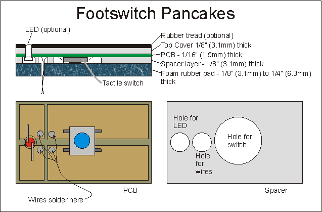
In the pancake, we use a readily available (Mouser and many other places) cheap (US$0.39) surface mount tactile switch. These switches are about 1/4" (6.3mm) square, and are rated for upwards of a hundred thousand to a million operations. But they're not going to withstand the pressure of us standing on them all by themselves. By a lucky coincidence, some of the commonest and cheapest tactile switches are 1/8" (3.1mm) thick when not activated. That happens to be one of the easiest to obtain thicknesses of many materials, notably acrylic sheet or plexiglass. If we make up a pancake of layers of materials, we can get switch activation and limitation of pressure on the switch. The basic pancake switch is shown in the illustration. For convenience, I've mounted the tactile switch and an indicator LED on a piece of PCB stock. The switch is mounted so the actuator button points down. I've cut relief holes into the plexiglass spacer layer for the tactile switch to fit into, for wires to exit into the effects box, and for powering an indicator LED. Tactile switches usually need only 0.1 to 0.2mm of travel to activate them. That's another secret to how this works. The layers, from the bottom, are :
The whole laminated unit is contact-cemented to the top of an enclosure, aligning a hole in the enclosure with the hole in the rubber for the wires to pass. When you press on the top of the stack, the incompressible upper layers force the spacer layer down onto the rubber foam layer. The flat surface of the spacer layer forces the rubber foam down uniformly except where is a relief hole over the tactile switch. The foam is less compressed there and that section actuates the tactile switch. The foam will not transmit enough force to squash the tactile switch and damage it. The indicator LED is a nice-to-have item, but is optional. Mounting a switch-state LED in the pancake switch is a handy way of not having to mount the LED in the enclosure separately, though. What will I need to make one?
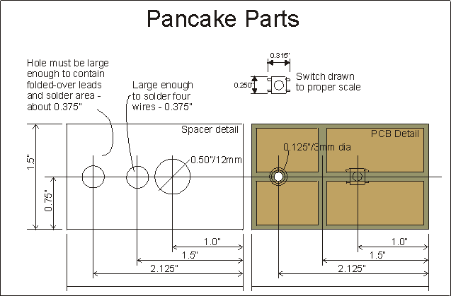
Cut to the chase Cut all the pieces you'll use in your pancake out of the base stock. I used 1/8" plexiglass for both the spacer and top cover layers, 1/16" copper clad for the PCB, and an old mouse pad. My pieces are 1.5" wide, 2.5" long. Cut all of the pieces to size first for as many pancakes as you'll be making. Try to cut them as close to the same size as possible, maybe using some kind of fixturing arrangement or a single master part for marking and cutting. This will save you time later in the cleanup and finishing phase. I personally would cut out all the pieces, then stack them all together and clamp them together with a C clamp and sand or file the edges of the stack to ensure that they're all the same size - it will save you time later. But this is optional. Once all the basic pieces are cut, mark and drill the holes in the spacer(s). The spacer holes have to be big enough so that the spacer does not contact anything that is not flat PCB stock, particularly the places where the LED leads and wires will be soldered onto the copper of the PCB. Otherwise, the spacer will not fit flat onto the PCB. Neatness doesn't necessarily count here. I've shown neatly-drilled and sliced holes, but the critical thing is just that the holes are big enough, but not so big that the tactile switch can be crushed by the foam pad. I marked and drilled small (0.090") holes in the center of the locations where I wanted holes in a master spacer, then stacked up the remaining seven spacer blanks, clamped them together, and gang-drilled the 0.090" pilot holes through all the remaining seven at once in my drill press. This let me ensure that all of them would be identical, and saved me drilling 24 holes. This is one place that making nearly-identical blanks is an advantage. With the pilot holes in the center of the actual hole locations drilled, drilling out the full sized holes is a snap. Next, make the PCB's. These things are so simple as to hardly qualify as printed circuit boards at all. What you really need is a slab of single sided or double sided board the same size as your overall pancake. The tactile switches have four legs, of which two pairs are already connected. Then you press the switch, all four become connected. The primary need in the PCB is to have one thin line etched away that will separate the two pairs of switch legs. The illustrations show this. You could clean the PCB stock, spray it with lacquer from a can, then scrape the lacquer away from the separating line. You don't even really need to etch. If you are good - and careful! - with a hobby knife, you can simply cut through the copper in two parallel lines and peel the thin strip of copper in the middle up. This is a pain, and a danger to fingers if your knife slips, but it can be done. To ensure correct registration between the spacer and the PCB, I made all my spacers first, then prepared and lacquer sprayed all my PCB blanks. I then traced the spacer holes lightly onto the lacquered PCB blanks in pencil. This let me ensure that the etching would indeed fall in places where the parts would clear the spacer. When the etching was done, I did the pencil-tracing trick again to ensure that my soldering would fall in a suitable suitable area and not hold up the spacer when I glued the parts together.
For a switch-only pancake, the one separation in the copper is all you need. If you decide to use the LED in the pancake, separate the copper plane into four areas by etching or peeling away a cross as shown in the sketch above, which is what I used for my prototype pancakes. Drill the hole in the PCB where the LED will poke through to show out the top. T- 3/4 packaged LEDs will just fit in a 1/8" (3mm) hole. Again, if you have made identical-sized PCB blanks, you can mark and drill one master PCB, then gang-drill the whole lot in one pass, and the results will also be identical. When the PCB blanks are etched and drilled, mark the places for the components using the spacers as guides and solder the components onto the PCB. For the SMT switches, clean and flux the place where ONE of the gull-wing switch legs will go. Tin this spot with a tiny dot of solder from the iron. If you have a well tinned iron and a well cleaned and fluxed spot, often just touching the iron to the right spot and heating the copper will transfer a small amount of solder to the spot you touch. When you have a dot of solder there for one leg, place the tactile switch with the leg in the right spot and reheat the leg slightly. This should solder it enough to hold it in place. Check the alignment with the spacer, and adjust the switch if needed by re-heating the single soldered leg and moving the switch slightly and repeating until you get it right. When it's right, solder the other three legs and then come back and re-solder the original with a bit more solder. An alternative placing technique is to place the spacer over the pcb, stick a dab of super-glue on the pcb where the switch's center will go, then place the switch in the dot of superglue in the proper alignment. When the super-glue is dry, you can solder the legs. If you're using an LED in the pancake, use the PCB as a drilling template to drill an aligned hole in the top cover and optional rubber tread. When this is done, stick the LED through the PCB hole (in the proper direction!) until the rim of the LED catches. Bend the leads over until they touch the copper of the PCB, trim the leads so they're inside the hole of the spacer, (re)check your orientation for anode and cathode, then solder the two leads down, trimming off any excess. When the PCB's, spacers and top covers are done and all fit together neatly in pancake piles with the edges aligned, get ready for some gluing. Glue me up, Scotty The layers are glued together with contact cement. Follow the instructions on the container of contact cement. This universally involves painting both surfaces to be joined, and then allowing both surfaces to dry. When the glue is dry, place a sheet of paper between the two surfaces, get them aligned, then slide the sheet of paper from between them, and press firmly together. The contact cement should grab instantly and permanently. Contact cement composition varies between brands, so test the cement you buy on your pancake materials to ensure that the contact cement will really grab and hold before investing a lot of work in a fully completed pancake. Like the template-based work before, some thought about how to align things will speed this up a lot and provide much neater results.
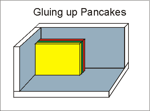
Set up a gluing jig - just a very square corner where you can stick parts and press them into square alignment as shown. Glue the PCB and spacers first. Put the spacer into the jig against the back "wall". Put the PCB in the jig, not touching the spacer, and verify that if you hold the PCB against the side "wall" and "floor" and slide it against the spacer, the PCB and spacer will fit together properly - flat, no gaps where solder or parts hold them apart. If that's not true, file or cut the spacer holes out until it is true. This step verifies the fit of the parts before gluing. Spread contact cement thinly onto the spacer, press it onto the copper face of the PCB, then immediately remove it. The spacer "prints" contact cement wherever it contacts the PCB. Smooth the contact cement to a thin, consistent layer on both the spacer and PCB, adding a bit more where it did not cover completely. Set the two pieces aside to dry before placing them together. LET THE CONTACT CEMENT DRY PROPERLY! When the two glued surfaces are dry, place the spacer in the gluing jig, glue side out. Put the PCB on the jig, but not touching the spacer, glue side toward the spacer. Verify that the parts are in the proper alignment, and holding the spacer against the back wall, slide the PCB along the floor and side wall until the two glued surfaces touch. Once they touch, they are friends for life, and you're not likely to be able to separate them nondistructively. Press them together to get lots of glue area contacted. Contact cement is named for this property - it glues on contact, not when it's wet. Repeat this with the top cover - verify the fit and alignment first, then glue, dry and place. If you've used the LED, ensure that the top cover hole for the LED fits the LED correctly in the jig. If not, drill out the top cover hole a bit until it does. When the fit is right, glue the pieces, let them dry, then use the jig to align and let them contact. Now do the rubber tread, if you are using that. Glue the foam rubber sheet on last. It's a good idea to hook an ohmmeter up to the switch leads and just sit the all-but-finished pancake onto the foam rubber layer on the floor and verify that pressing it does in fact operate the switch. At this stage, if the switch is too sensitive, you can cut away some of the foam rubber just under the switch to adjust how hard you have to step on it to activate the switch. This whole gluing process should by now have really brought home the importance of cutting and truing the blank pieces to the same size. You're likely to have wound up with pancakes that don't ... quite... stack up neatly. Never fear - the sandpaper's here... Get out your sheet of coarse sandpaper. Place the sandpaper on a flat surface, and move the edge of your pancake over the sandpaper until the edge is all trued up and level, if slightly rough from the sandpaper. Do all four edges. You'll now have a neatly edged, all same size stack. Use finer grades of sandpaper and repeat until you have a finish on the edges that you can live with. The coarse sandpaper will also do a good job of rounding the corners slightly if you like. If you're persistent, you can go through successively finer sandpaper grits until you have polished edges. Let's mount up, boys So how do you mount this mess on an enclosure? There are several ways, but the simplest is - yep, contact cement. The pancake approach only needs a flat surface that will support some foot pressure. Make your pancakes with the enclosure layout in mind. They can be fairly small - 1" x 1" (25mm x 25mm) will work just fine for a pancake. They can actually be almost any outline as well. It helps a lot if you've made one extra piece of plastic the size of a spacer but with a hole where the wires need to come through the foam rubber into the enclosure. That way you can use this as a template to mark where the pancake will go and where to drill the hole for the wires from the switch and optional LED to enter the enclosure. Another way is to add yet another layer to the pancake, a thicker layer of plastic, maybe 3/16" or more, underneath the foam rubber layer. This layer can be thick enough to be drilled and tapped, so that it can be screwed to the enclosure instead of being glued. There are many other ways to mount these.
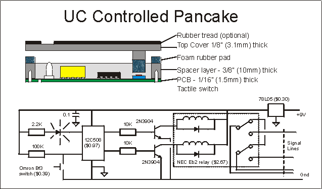
Here's another way to do it - put a miniature latching relay and programmable microcontroller inside the pancake. To do this, you just use a thicker spacer which is almost entirely cut away inside so there's room for a miniature relay and some electronics. The NEC EB2 series is cheap and effective. The PIC 12C508 controller costs $1.50 for one, and $0.97 each if you buy 25 (and they make dynamite replacements for 555's!). This controller takes over the entire task of reading the tactile switch, keeping track of on/off state, managing an indicator LED, and flipping the set/reset pulses into the latching relay. The 508 itself pulls 1 ma of current - less than the LED! - so it's not going to drain your batteries all by itself. The relay sets and resets with a pulse of 30ma for 20 milliseconds when it changes, so that's not going to eat your batteries up either. The relay provides metal-to-metal true bypass, and the controller manages the care and feeding of the relay. Total cost? Probably under $5, and some labor. This setup requires more detailed work on the spacer and top cover. The spacer has to be cut out to fit all the electronics, and the top cover has to have a "presser" and a chunk of foam rubber glued to it to press the tactile switch. Fortunately, this is not much more advanced work than making a generic pancake. Those of you who read GEO will recognize that this is the "Latching Relay Bypass", but with the CMOS hex inverter chip replaced by the microcontroller. That would not ordinarily seem smart, but with an eight pin controller that only costs $0.50 to $0.75 more than the (bigger!) 16 pin CMOS chip, it gets really reasonable. Great! I built one! Now what can I do with it? Good question, but a little out of order. I guess this question properly belongs at the front of the article. What you have here is a sturdy, customizable, foot actuated momentary switch good for many thousands of operations, and with an optional LED indicator. This is ideal for use with the latching relay bypass, as the foot switch in the ASMOP 1 foot controller, or with the CD4053 CMOS bypass circuits, as well as several other things. It's usable as is for any momentary switching requirements that need only a simple momentary switch closure. Any fancier uses will require additional circuitry to do the heavy lifting. I developed this to use with my prototype of the ASMOP 1 remote foot switch effects controller. I thought you would like to see some of the good stuff early, though. R.G.
|


