|
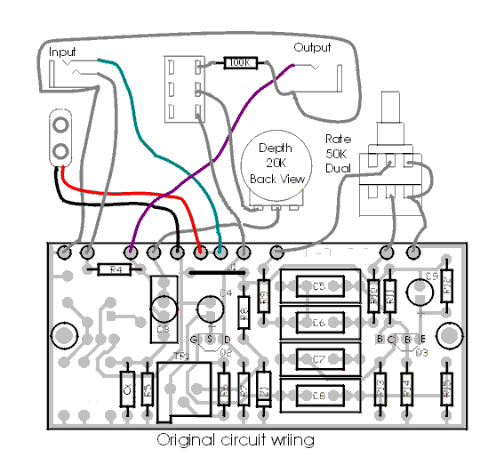
Here's how to wire it for the original circuit. You just leave out the parts for the buffer. R4 is rotated 90 degrees so it bridges from the input to the output, as in the original. Again, leave out D1 and D2. The wiring on the depth pot is shifted a bit, and the 100K resistor (R16) which attenuates the signal in the "bypass" mode is added between the stomp switch and the output jack ground, not on the board. Notice that half of the stomp switch is now unused, and could be used to switch an LED on for status. Also note that this is not true bypass. But at least it's original 8-)
Here's the PDF file for printing a toner transfer of the PCB pattern, and here's the parts list.
(Previous Page) (1) (2) (3) (4) (5) (6)
|

