Copyright 2002 R.G. Keen. All rights reserved.

Ever look at a circuit and wonder why they loaded all that junk onto it? Or just couldn't figure out what some of the parts did, and couldn't relate them to any opamp circuits compendium you have?
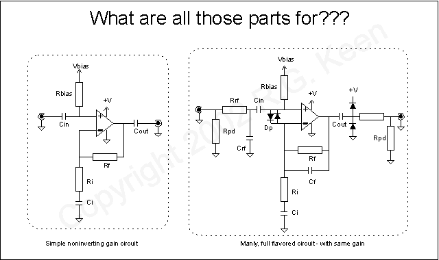
Here's part of what might be confusing you. The bottom line is usually protection or "polite" behavior. The two circuits above do the same thing, and have the same gain if Rf, Ri, and Rbias are the same values. The one on the right has a lot more stuff in it. Let's take a walk through it.
Starting at the input, we run into an easy one - Rpd. This is the pull-down resistor we're so familiar with from stompbox practice. It and the matching one at the output are politeness parts. They're there to pull the leakage from Cin and Cout down to ground so you don't get a pop when a hard metal switch bypasses and un-bypasses the circuit.
Then there's Rrf. That, and Crf form a radio frequency (rf!) lowpass filter to dissipate any radio-station pickup that might find its way to the input. You'll sometimes see Crf used without Rrf. That's bad practice. It relies on something further to the left/input side of the circuit to impede the radio waves. A real, honest-to-Pete resistor does a much more reliable job. Sometimes Crf by itself makes radio interference worse by tuning the radio waves and actually presenting more to the input.
Cin: finally, a part we see in both places. Cin sets the input frequency low end rolloff with Rbias. The frequency where the response is half power will be F = 1/(2*pi*Rbias*Cin), and rolls off as the frequency goes lower. Every frequency above that is passed by Cin.
Dp: protection diodes. See "When Good Opamps Go Bad". These two diodes, along with Rrf, protect the delicate input transistors from spikes, trash, and overvoltages on the input.
Rbias: provides the (hopefully tiny) DC bias current to the noninverting input of the opamp, and also sets the effective input impedance.
Rf and Ri: set gain. As shown, the gain in the middle between the low and high frequency rolloffs is Av= 1+ Rf/Ri
Ci: sets another low frequency rolloff. This one is calculated the same as the one caused by Cin/Rbias, but may have a vastly different value, depending on the values chosen. Good practice usually sets one of these far away from the other and lets a single rolloff set the low frequency behavior of the amp.
Cf: sets the high frequency response. By shunting Rf, Cf lowers the amp's gain towards 1 from the value set by Rf/Ri. This rolloff starts at the frequency where F = 1/(2*pi*Rf*Cf).
Cout: same function, both places. Blocks the DC level from the output pin. Also introduces yet another low frequency rolloff point. Gad, they're everwhere!
Diodes to +v and ground: these protect the opamp from any inductive load that might be connected by shunting any inductive spikes to the power supplies. The current of these spikes is limited by the resistance in series with output. This same resistor isolates the opamp output from highly capacitive loads that could make the opamp unstable, and prevents overcurrents from damaging the opamp, if needed.
Whew!
So, do you need all that mess all the time? Probably not. The input stuff protects inputs, the output stuff protects outputs; maybe only the appropriate section needs grafted in. Cf can help tame high end response wherever you need it.
But they sure make it confusing, huh?
R.G.