Copyright 2000-2006 R.G. Keen. All rights reserved. No permission for local copies or reposting from sites other than http://www.geofex.com.
This project involves wiring and working with AC mains line voltage. You MUST pay strict attention to safety warnings and MUST be able to do the wiring safely. This article will not teach you to do that - you have to come prepared to do that on your own. If you don't already know how to do it safely, do not try this project.
| Ever get just totally screaming frustrated with *both*
replacing batteries in effects on your pedalboard *and* with the hum
from an AC-adapter power supply? Do something about it with the Spyder.
Why do pedalboards hum? It's possible that you have a bum power supply. If your power supply is a salvaged wall wart that puts out DC, it may or may not have an internal filter. It may or may not have an internal regulator to make the power smooth. Both of these will make for bad, possibly insufferable hum. But if you have a good power supply and it still hums, it may be ground loops. The simplest explanation of ground loops in the context of pedalboards is that the ground conductors of the whole mess of shields, boxes and cords can pick up the all-pervasive 60 (or 50!) Hz power line field just like the coils of wire in a pickup produce a voltage when the strings wiggle the magnet's fields around them. It is especially pernicious when you have high gain distortion devices and ill-shielded wall-wart power supplies hooked up right together on a pedalboard. The loop actually forms when two effects boxes are connected by the shield wires in the cord connecting them, and each also has a ground connection to a common power supply. Looking at the illustration below, we see the two ground loops formed with three effects and one power supply (only the ground conductors are shown). This loop of conductor happily picks up the 60Hz power |
line leakage field, and since all effects are single ended, they have no
common mode noise rejection, so the hum is amplified with the signal.
The amount of hum pickup on any coil of wire depend on how many turns, but also on how big the loop is. If you make the loops tiny, like a single supply very close to the pedals, you may not get a noticeable hum. If you have several effects inside one big shielded box and one power supply in there, chances are you're going to be OK. But big external loops are going to be a problem. So how do we bust the hum? Easy - break the loops. One highly effective way is to break the shield lines at one end of each signal cord connecting the effects. The effects are still grounded together by the connection to a common "ground" at the AC power adapter. This method has its drawbacks because the modified cords can cause problems if they're ever used where there isn't a common power supply ground to keep everything at the same AC and DC ground potential. Going back to batteries means changing out all the cords to keep from having even bigger hum problems. Another way is the Spyder. The Spyder does the straightforward approach of making many individual power supplies that do NOT have a common ground, or any common connection at all. This means that the loops are never formed, the signal cables are intact, and that the hum goes away. |
|
This isn't rocket science, by any means. The key ingredient here is multiple isolated power supplies. This lets us break the common ground connection which completes the ground loops. Batteries do this very well, because batteries are completely floating. Another way is with multiple isolated transformer secondaries which feed multiple isolated rectifier/filter/regulator sections. There is no connection of the power supplies at the main power unit, so the hum loop cannot form. |
There are two straightforward ways to do this. One is with an eight-legged (OK, OK, eight secondary!) transformer as shown immediately below. We just make one 9V output per secondary. No common connections, no hum loops. The second way is with eight individual transformers. |
|
Each of these ways have their own advantages and disadvantages. The multiple transformer way is easy to start small and work up to only as many power supplies as you need. It does, however, get more expensive as the number of supply outputs goes up. Suitable transformers are a bargain at Mouser, as #41PG006 is a 12V/0.06A transformer for under US$3.00. If you really, truly need only three power outputs, then the $9.00 for the three transformers is fine. You can wind up your own transformer from a flat-pack transformer using the instructions at the end of this article, and that may be a very cheap way to do this if you can find a flat pack transformer cheap or for free. The secondary voltages don't matter for this transformer, because you would remove them entirely. All you're interested in is the primaries. You can, however find an already-made nine output transformer suitable for this purpose. |
A few years after I wrote up this article, Ted Weber started offering this transformer. It's a really good deal! Go to https://weberspeakerscom.secure.powweb.com/store/magnetic.htm and go all the way to the bottom to find WPDLXFMR-1, which has eight 11Vac secondaries for powering 9V pedals just as shown in this article, and one 9Vac output for powering pedals that need 9Vac. At the time of this update, it sells for $15.00, which is a GREAT deal. It's such a good deal that I think it's a little silly to go to the trouble and possible danger of winding your own if you don't have to. Buy Ted's transformer unless you have some darn good reasons not to. In this, as in the rest of life, you have to review your personal needs and choose accordingly. |
|
An alert reader has already asked if the regulators in the Spyder could be made to simulate the response of an almost-exhausted battery. Yes, it can, the same way the pedalboard power supply at other places on GEO can be made to. To do this successfully, you have to use an adjustable regulator. The LM317L does this very |
well. The 317L sets you set its output voltage by means of resistors. I've shown two fixed and one adjustable resistor here; with the values shown, it will put out 7.0 to 9.5V. The variable resistor in series with the regulator output simulates the increased internal resistance of an almost flat battery. It can be tweaked from 0 (fresh battery) to 200 ohms (dying battery). |
|
Mouser sells a 12V/100ma tranformer for $2.28
in 10's.
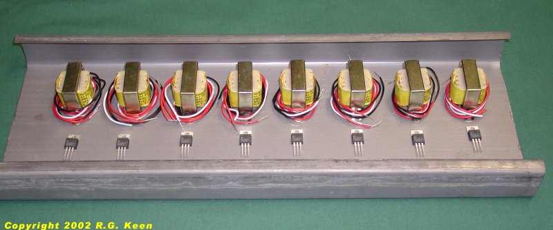
Below is a picture of eight of the ten being pre-fitted inside a section of steel stud channel before I drill and start soldering. As you can see, the fit is nice, and all of the circuits will go in there just fine. |
|
Instructions for a Do-It-Yourself Multi-Winding Spyder Transformer
If you're a stubborn do-it-yourselfer, you can make your own transformer for the Spyder instead of buying either eight small ones or the nine-winding job. This involves working with AC line voltage. You MUST pay strict attention to safety warnings and MUST be able to do the wiring safely. This article will not teach you to do that - you have to come prepared to do that on your own. If you don't already know how to do it safely, don't try this project. It is far safer and in many cases cheaper to buy the transformer offered by Ted Weber. Only consider winding your own if there are circumstances which make this your only good option, and even then be very certain you can do this safely before trying it at all.
Making your own Spyder transformer involves finding a flat-pack style transformer to work on and then replacing the secondary windings.
If you buy a suiltable flat-pack transfomer new, it will cost about $12 - $15 in the USA. You will have to do some hand work on it, as well as (probably) buying magnet wire for winding, which can easily add another $10-$15 if you don't already have the magnet wire. If you have to buy the transfomer and wire, you're out $24-30 before you start, and the Ted Weber transformer is only $15. If you buy eight of the Mouse transfomers, you've spent about $22. You have to make your own decisions!
|
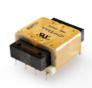
This picture below is linked in from the Globalspec site. It's a shot of one of Triad's "Flat Pack" line of transformers. For powering a pedalboard, these are about the ideal form factor. They are semi-toroidal, but more importantly, they can be modified readily and fairly safely. All of the Flat Pack transformers have dual 115V primaries and dual secondaries. |
They cost about US$12 at the time of this writing. What is not clear from this sketch is that the primaries and secondaries are separated by an insulating spacer that is an integral part of the bobbin. With some care, you can cut away all of the secondary wire and re-wind new secondaries with NO changes to the primaries. This is an important safety feature. |
|
This is a cutaway diagram of the Flat Packs. As you can see the primary (dangerous!!) windings (in orange) are kept in their own winding area, and the secondaries (in green) are in their own area. As long as you do not disturb or modify the primaries in any way, the important safety features of the transformer remain intact. Building a Spyder Transformer First get a 6VA or larger Flatpack. Mouser # 553-FP-20-300 is what I used. What matters here is the power rating of the transformer. 6VA is barely enough. The next bigger size would be better. If you are salvaging a transformer corpse to work on, measure the physical size of the unit and make sure it's as big or bigger than this one. I carefully inspected the windings to be sure that I knew which were primary and which secondary windings, using the pinout drawings from Magnetek. Then I unwound the outer tape layer from the secondary areas (which are side by side, as shown above). I used small diagonal cutters to clip out all the wires in one of the secondary bobbin areas, and hand-wound in exactly ten turns of wire. I then did a quick open circuit test of the voltage on the ten turns of wire. This turned out to be 0.30Vac. Since the same volts per turn will occur on every winding, This experiment told me that each turn has an open circuit voltage of 30mv, or about 3V/100 turns. From this information I could calculate the necessary turns for the right secondary voltages on the eight secondaries. |
Let's do the math quickly. We need 9Vdc out after a regulator. The regulator needs a minimum of 2V for its internal voltage drops. To this we add the allowable ripple voltage on the raw DC, and to this we add the 1.4V we lose in diodes rectifying the AC to DC. Let's say that we think we can get by with 1V of ripple. So we have 9V +2V +1V +1.4V = 13.4V. This is the required peak voltage on the secondary AC. We'll assume that this actually occurs at a 10% low AC line, so the actual nominal voltage is 13.4/0.9 = 14.9V peak. To get the RMS voltage, we divide by the square root of two, 1.414 to get the AC secondary voltage of 10.5Vac. The number of turns is then 10.5Vac/.03 V/t = 350 turns of wire. Since this was an absolute minimum, I decided to round the number of turns up to 400. Each secondary needs 400 turns of wire, and we need eight secondaries, or four per secondary bobbin. A little measurement of the bobbin space and some math showed that #36 wire was a tight fit, and #37 is an easy fit for 1600 turns (four secondaries of 400 turns) on this bobbin. I had a spool of #36 in my garage, so I used it. Mouser Electronics does not stock #36 or #37. I will include sources for magnet wire in upcoming revisions. |
|
It's entirely possible to set up a holder/spindle for the bobbin, a handle to wind it with, and so on. I didn't bother with that. I have an assortment of screwdrivers in my garage, one of which happened to be a loose rotating fit inside the hole in the nylon bobbins. |
I clamped the screwdriver in my bench vice with enough shaft extending to hold the bobbin and turn it with one hand. I used another screwdriver and a C clamp to hold the magnet wire spool on the workbench leg below the bobbing being wound. The mounting legs left on the bobbin chewed up my fingers a bit, but it worked well enough. |