Copyright 1999 R.G. Keen. All rights reserved. No permission for serving from other than http://www.geofex.com.
I've had several questions about making an effects order switcher, a box that you can stomp and reverse the linear order of two effects plugged into it. This is not too taxing a task, so I thought I'd use it as a way to convey the many way designs can be implemented and some of the considerations that go into design.
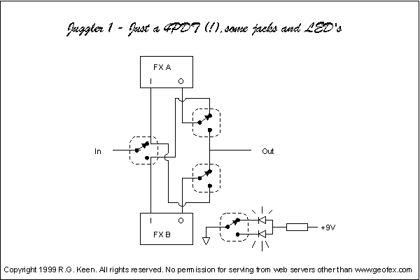
To do a minimal job of reversing the order of two effects, you have to have a way to selectably connect either effect input to the overall box input, and either output to the overall box output, and at the same time, connect the input and output of the effects NOT connected to the input or output of the reverser. That's good and confusing, so let's look at a schematic.

The Juggler 1 shows the minimal arrangement. For clarity in following where the signals go, I've not included the various jacks. The input to the juggler comes into the first switch section and is selectably routed to either FX A or FX B by the two throws of the first section of the multi-section switch. The output from FX A goes to the pole of a second switch section. Likewise, the output of FX B goes to the pole of a third section of the switch. Two throws of the second and third switch sections are connected together and tied to the Juggler's output jack. The output throws are phased so that when one is connected to the output, the other is not. Finally, the unused throws of the second and third section are cross coupled back to the throws of the first section so that when the ouput of an effect is NOT connected to the output, it's connected to the input of the other effect. Whew!
While that is enough to do just the minimal job, we would presumably like to know whether the effects are in A-->B order or B-->A order. That's the job of the fourth switch section. It's pole is connected to ground, and the two throws select LED's so that you have an indicator of which way the reversal is going.
So - all you really need is a 4PDT stomp switch, a couple of LED's, a resistor and some wire. The problem is that pesky 4PDT. You think DPDT's are hard to find? Hah! Actually, there is one 4PDT made, but they are expensive, delicate, and hard to find. Expect to spend $15 - $20 for one if you can find it.
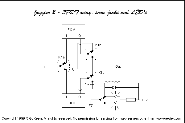
We should be able to do better. The next try is the Juggler 2.

The Juggler 2 uses a 3PDT or 4PDT miniature relay to do all the heavy switching, and a SPDT stomp switch to drive the relay's coil. This is better, as 3PDT or 4PDT miniature relays can be had for about $5-$7 and an SPDT stomp switch is about $3. Notice that you could use an SPST stomp switch and only light an LED in one direction so it could be even cheaper.
A variation on the same theme is that we note that the relay coil uses gobs of current, and a 9V battery won't last long. To fix that, we can use a latching relay, controlled by some CMOS logic to do the same job. That is the same schematic shown in the New Effects section, so I haven't drawn a new schematic. The signal switching is the same as that shown here, the coil switching is as shown for the latching relay interface for stompboxes. Latching relays are about $1 more, but now you can use a CMOS inverter logic chip for $0.50 and a momentary footswitch.
Notice what we're doing here. There is a certain minimal function - the signal switching paths - that must be maintained, and some way to select and indicate which path is being taken. Any design that does both of these well enough is a good design, and we get to trade off costs.
Can we do better than that? Maybe.

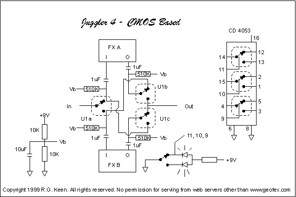
The Juggler 4 is a CMOS based effects order switcher. The triple pole, double throw switch is the CD4053 analog multiplexer.
What's that? You say that CMOS switches pop, click, and otherwise sound bad?
Well, maybe. The popping is usually a problem of failing to take proper care with some chip requirement. While it is true that the on-resistance of the common CMOS multiplexers changes with signal level, we can get around about 99% of the problem by biasing the CMOS input and output pins up to 1/2 the supply voltage and coupling the signal to the pins with capacitors. I've done exactly this with the CD4053 on high gain distortion pedals. Done properly, it does not pop or cause tone loss. True it's not a perfect switch, but it's awfully good value for the money. I have net to find someone who can reliably tell it from a true bypass connection. Some people can get it right 60% or so of the time, but they're a long way from being certain.
In return for using a $0.50 CMOS chip and some R's and C's, we now get to use the same SPDT or SPST footswitch, but now the whole signal switching mess reduces to one very cheap IC. If you want an even cheaper version, you can use one CMOS inverter package to implement a flipflop and use a momentary footswitch to save even more money.
Notice that we used the same signal path wiring and functions, did it in three different technologies, and took advantage of several different footswitching technologies. They all act the same, but they have different advantages and costs.
There's always more than one way to skin a cat - or a stomp switch.