Copyright 2001 R.G. Keen. All rights reserved. No permission for local copies or serving from web pages other than http://www.geofex.com.
Sequenced wah circuits have been popular recently. As pointed out in "The Technology of Wah Pedals", all you need to do to change the frequency of a wah pedal for all the common wah types is to have some way of changing a resistance. In most foot operated wahs, this is done with a mechanical arrangement to allow your foot to cause rotation of a controlling potentiometer.
There are other ways, though. It's quite feasible to switch between discrete values of resistance to get changes in the wah (or other effect) that you're controlling. A manual rotary switch works quite well for this. However, we can take a hint from our synthesizer brothers and use a sequencer, an electronic means of stepping from one value to another.

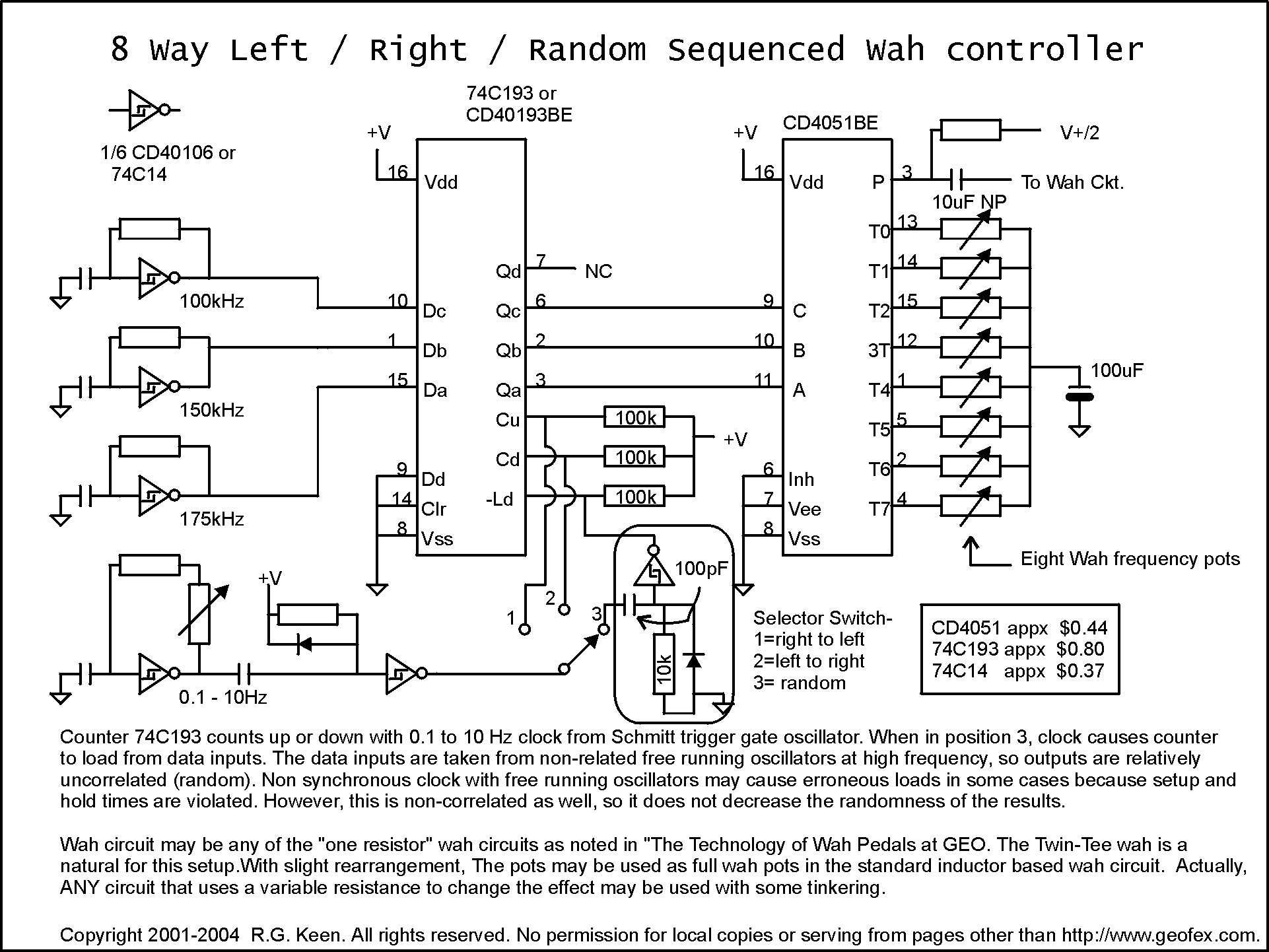
Here's one fairly neat way to do this with simple, cheap logic. The CD4051 is an electronic single pole, eight-throw (SP8T) switch. It conducts analog signals from the single pole on pin 3 to any selected throw. The exact throw is selected by the signals on pins 9, 10, and 11. These binary logic signals represent the binary versions of the numbers 0, 1, 2...7. When a binary 1 is presented (001), then throw 1 is activated and connected to the pole with a resistance of about 200 ohms internal to the switch. When a binary 5 is presented (101), throw 5 is connected. If we hook up a row of pots to the throws, a pot is selected with each throw.
By hooking a binary counter to the selector pins, we can make the 4051 select throw 0, 1, 2...7, 0, 1... and count through that sequence forever.
I have shown the selector and pots as isolated through capacitors and pulled to 1/2 of V+. This is the easiest way to get good operation of the selector without switching glitches. There are other ways to connect this as well, but this is the simplest and most straightforward.
I chose the CD40193/74C193 CMOS counter because it also has some other tricks you can play. It not only counts up, it counts down as well. So the sequencer will count through the row of pots left to right and right to left as well by selecting the correct place to put the clock pulses.
In addition, the '193 will load any digital data you like through its load inputs. If we present a random binary word there and pulse the "load" pin instead of the clock up or clock down pins, the counter will set its output pins to whatever binary signal was at the data inputs when the load pin changed. I originally used the outputs of three different high frequency counters on those pins as shown in the diagram above. If the counters are unrelated, the binary data words will be fairly random - not completely, but good enough to sound random to humans. That idea hasn't turned out all that well for a number of experimenters, so I developed a different and much more random generator. That is the CMOS Pseudorandom Generator. I recommend using this instead.
The "random wah" was recently the subject of a lot of discussion in the effects community, and this is a quick and easy way to get it.
The three high frequency counters and the main sequencing clock are made from sections of a CMOS hex Schmitt inverter, the CD40106 or the 74C14. If the signal on the output of an inverter is high, its output must be low, so the input capacitor is low. The capacitor will charge up through the feedback resistor, and as soon as it hits the upper voltage threshold, the inverter will change its output to low, and the capacitor will now charge down through the feedback resistor. When it gets down to the lower Schmitt threshold, the inverter flips again. It's a very easy and effective way to get a bunch of oscillators. The frequency is entirely determined by the feedback resistor and the timing capacitor.
The Schmitt inverter driving the sequence selector switch is used as a half-monostable. It is coupled to the master clock through the series capacitor. This capacitor is small, so only the positive and negative-going edges of the clock signal are passed through to the inverter. The positive going edges are "swallowed" by the resistor/diode combination on its input, so only the negative-going edges of the master clock get to the input of the inverter. This causes the inverter to make a very narrow positive-going pulse on its output. The schmitt trigger action of the gate makes it a very clean, sharp pulse, ideal for clocking the counter or causing it to load.
Although the wah has been used as an example for this sequencer, almost any effect characteristic that can be set by changing a series resistor can be sequenced by this technique. The whole sequencer can be built on perfboard quite inexpensively, and can add whole new dimension to effects.