| I've seen several implementations of a wah pedal with
vacuum tubes now. So far, they all use circuits with some problems to do
the bandpass filtering a wah needs, and none of them use the
tried-and-true variable gain/capacitance approach of the old Vox Wah.
I think this comes from a lack of understanding of how that circuit works. It's easy and simple to make a wah with almost any gain block in that configuration. No huge metal multiplate capacitors or multiple feedback filter circuits are needed. So I designed up the following circuit to try it out. Be advised - I have not built this yet, so it must be considered experimental. However, I've simulated it six ways from Sunday, and can't find any flaws in it yet. I'd welcome someone trying it and reporting results.
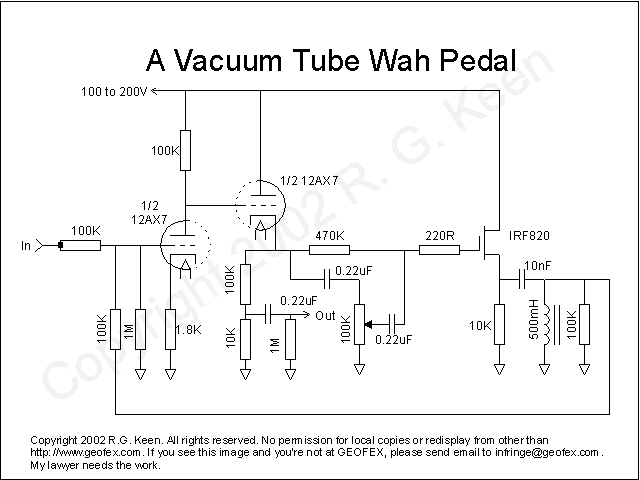
Operation is exactly as described in "The Technology of Wah Pedals". The first 12AX7 section is set up as a gain stage. The second half is used as a cathode follower to isolate the first stage from loading and keep the gain high. The follower drives two loads: the output path through the 100K/10K divider and the 0.22uF cap to the output, and the feedback path through the 0.22uF cap, 100K wah pot, and IRF820 MOSFET. The MOSFET is there just as an economy move. My experimentation has led me to believe that with few exceptions, you can't hear the difference between tube and MOSFET for the very limited case of cathode follower versus source follower. This lets you save one half-tube; in this case, there would be a whole additional tube needed. You could use a cathode follower if you like. The exact circuit will work. The MOSFET is biased by the DC on the cathode of the second 12AX7 section, and fed signal through the wah pot and 0.22uF capacitor. It buffers this variable amount of signal and couples it into the 10nF (0.01uF) capacitor and into the inductor. This forms a basic series resonant circuit. The resonant signal is fed back to the input through the 100K resistor to the grid of the first 12AX7 stage, and is mixed with the input signal which has its own 100K resistor. No one who ever did circuit simulation and then had to build the circuit ever trusts simulators completely again. Feed a simulator a plausible set of stuff, and it may lie, lie, lie. However, after a few cycles of this, you learn how to feed a circuit simulator stuff that will lessen its ability to lie. That's what I'm going on here. You might have to bypass the 1.8K cathode resistor on the first stage, and also adjust the value of the 10nF resonance cap. The resonance is very sharp, and you might prefer it with a Q-lowering resistor strapped across the inductor. These are all tuning measures, and follow the guides laid out in "Technology of Way Pedals." Since putting this article up, I've had email from people who did similar things. Turns out that the circuit will probably work fine, but the inductor will be very sensitive to hum. When I build my prototype, I'll do the following to control that:
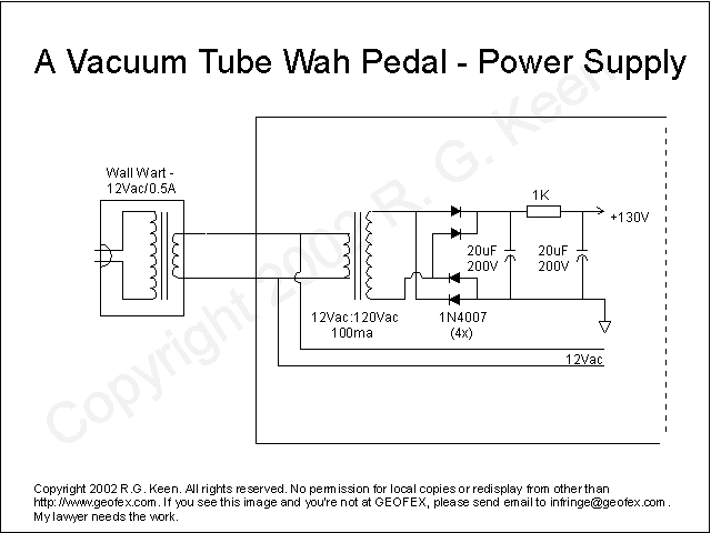
Power supply Here's a suitable power supply. I get the main power transformer outside the chassis by using a 12Vac, 1/2A wall wart. This runs the 12V filament/heaters of the tube, and also powers a mini-transformer inside the chassis which runs backwards. The 12V "secondary" of the mini-power transformer gets 12Vac and steps it up to 120Vac to make the high voltage DC for the plate supply. The mini-transformer is a stock Mouser item, 12Vac @ 0.100A, about $2.75 each. 12Vac wall warts are wherever you find them.
Other than that, the power supply is utterly simplistic - full wave rectifier feeding a filter cap, then an R-C filtering network. So - ya wanna build a tube-based wah pedal???
R.G. |

