| With good tubes expensive and hard to find, it makes
sense to use non-tube solutions to do "housekeeping" functions
in guitar amps. This lets us reserve those hard-to-find great sounding
tubes for the place where they really matter - the places that audio is
actually handled.
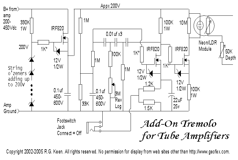
Here's a quickie that lets you save a tube. The foundation of the circuit is the neon/LDR style tremolo from many Fender guitar amps. This circuit uses half a 12AX7 to form a phase shift oscillator and a second half to drive a neon bulb with a variable current. This variable current makes a sympathetically varying amount of light fall on a light dependent resistor (LDR). The LDR then shunts some point in the signal chain to cause a volume variation in time with the LFO. I used International Rectifier IRF820 power MOSFETs to replace the tube functions. Since audio doesn't go there, it's hard to imagine how the silicon substitution could harm audio tone. The middle IRF820 is the oscillator. This circuit is right out of the Fender circuit except that there is a provision to bias the MOSFET slightly on since MOSFETs are enhancement devices that need an external bias voltage. Triodes are depletion mode devices that will self bias. The 1M/33K resistor divider provides a few volts of forward bias to the oscillator MOSFET. The oscillator is turned on an off by a remote footswitch stops the oscillation. The footswitch twiddles the bias on the oscillator to turn the oscillator MOSFET full on. This turns the neon driver fully off and prevents it from sucking any volume from the amp being controlled, as the Fender circuit did in a slightly different way. The 12V zener diodes are there to prevent high voltages from killing the MOSFETs by puncturing their gate oxides. The 1K resistors are there to keep the MOSFETs from oscillating at hundreds of megahertz, and they should be placed as close to the gate pin as you can get them. In every way except those, the MOSFETs are more rugged even than the tubes they replace. The phase shift oscillator otherwise is exactly the Fender circuit.
Fender used a second half-12AX7 in a gain configuration to drive the neon bulb. The differences in tube and MOSFET biasing make this configuration not work. However, since the oscillator MOSFET will happily make a 200V sine wave, the extra gain is not needed. Simply attaching the third MOSFET to the drain of the oscillator MOSFET in a follower configuration works fine, and the 100K resistor value from the tube circuit can be moved to the source of the MOSFET to limit current. This makes the current through the neon proportional to the voltage from the LFO. The neon and its parallel 10M resistor remain on the B+ side of the circuit. This setup would normally be all that's needed, except that the B+ voltage varies in amps. Biasing the LFO MOSFET to near the middle of the available B+ voltage range on its drain is a good idea for best oscillator swing. However, adjusting that requires adjusting the 1M/33K biasing divider, perhaps as the B+ varies. It's going to be different for every amp. A simplifying solution is to regulate the B+ going to the circuit. The first MOSFET in the upper left hand corner takes B+ voltages from 200V on up to over 400V and regulates them to 200V. It does this by means of acting as a source follower for the resistor/zener string on its gate. The gate is held at +200V for all B+ voltages over 200. The MOSFET source will not be more than 3V or so lower than the gate, even if the drain is hundreds of volts higher. This lets you adjust the 1M/33K divider for the particular oscillator MOSFET if needed, and then have the circuit work in all amps. Notice that I have cryptically called that a string o' zeners. You can use any combination of zeners that add up to 200V there. Since single 200V zeners are rare, you could use two 100V zeners, ten 20V zeners, two 75's and a 50, etc. The dissipation is not a concern if you use 1/2 zeners. If you build one of these, remember - the voltage on those pretty metallic tabs sticking up from the IRF820's is hundreds of volts, and it is NOT pleasant or safe to touch them. You can be damaged badly or killed by the high voltage, so wire it up safely and keep hands off. Although the Fender application uses the LDR to load the signal in the audio path of an amp, it's possible to use this circuit other ways. Some amps use the tremolo oscillator to waggle a bias voltage around. That can be accommodated by taking the circuit output from the source of the third MOSFET through a capacitor to the bias voltage you want to modulate. Since there's potentially 200V of signal there, you will have to make the 100K source resistor be a divider to reduce the LFO signal level to one compatible with your circuit. This circuit really lends itself to adding tremolo to amps which don't have one. A single small circuit board gets that Fender "vibrato" mojo happening, no additional tubes needed. If your amp already has tremolo, you can replace the circuit with this one and free up both halves of a 12AX7 for further mods. R.G. updated 2/18/2005 |
