Note Processing for Guitar Effects
Copyright 2001 R.G. Keen. All rights reserved. No permission
for local copies or serving from hosts other than http://www.geofex.com.
What's a "note"?
Seems like a silly question, because we can clearly hear notes
in music, so it should be easy, right? While defining what a note is to a human
might be easy, designing a circuit to pick out a note in a flow of music turns
out to be surprisingly hard. Us human hearers happen to be probably the best
pattern-matching intelligence on the planet, and we can readily dig audio
signals out of noise and other bad conditions that would baffle instrumentation.
As effects makers, we are often interested in making something
happen on a per-note basis. For instance, the quality of "sustain" is
intimately tied to the length of a note. To get greater sustain, a note has to
extend for a longer time without much change in its tonal qualities. The common
sustainers manage to change the relative gain applied to signal, increasing it
as the signal dies away. Auto-wah effects derive a signal that is proportional
to the instantaneous loudness of a note, and change some property of a
filter based on that loudness. Noise gates just determine when there is and is
not a note, and turn the signal gain down to nil when there is no note playing.
There are lots of other things we could do as tinkerers if we had a good way to
extract information about notes from the flow of signal that comes out of a
guitar.
Quite a lot of effects circuits come from a history with either
organs or their souped up descendants, synthesizers. These instruments have the
luxury of knowing exactly all the qualities of any given note, because they
electronically synthesize the note itself. Guitar effects have a harder job
because we can only determine things about notes while they are actually
occurring, and have no information except the signal itself.
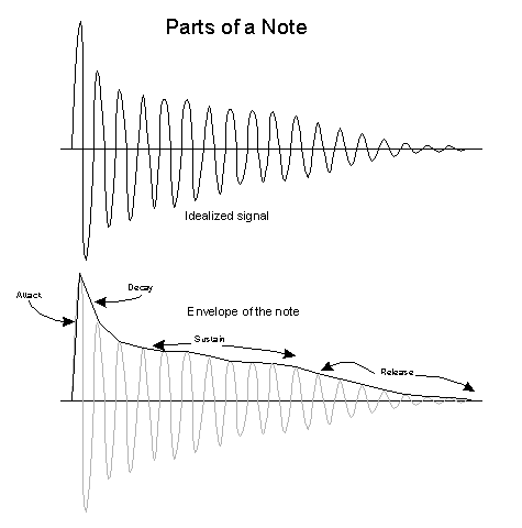 So what's in a
note? The sketch at left shows what might be an idealized version of an
archetypical note. The very first signal we get, starting from nil, is a loud
transient. This might correspond to the pick attack, when a guitar pick pulls
the string massively further than it will vibrate normally. That initial
loudness attack decays very quickly to the sustaining level of the note, where
the note volume decays at a slower rate. When the musician ends the note, there
may be other mechanisms that make the note sound for a little bit after the
musician ended it. This is usually a much faster die off than the sustain part
of the note.
The signal contains loudness information, frequency information,
and in any real instrument harmonics and some noise. The simplified example does
not do justice to a real guitar note, which is much less of a sine wave and more
of a crooked sawtooth, at least in the simple case where only one note has been
struck. If two or more strings have been played, both base frequencies and both
sets of harmonics are present, and the supposed regularity gets really rough.
Frequency and harmonics are very hard to extract useful info from, so almost all
note processing goes for the amplitude envelope.
Organ and synth makers long ago standardized on the definitions
of attack, decay, sustain, and release to describe the loudness dynamics of
notes. All of these things are characteristics of normal acoustic instruments.
For instance, horns have a very prominent attack/decay transient, known in the
musicology biz as a "horn blip" - how's that for original? Some
instruments have almost no attack transient, like a softly bowed violin. Some
instruments have little or no release, well made electric guitars being one of
them if you let the string simply ring until it dies out. However, on an acoustic guitar,
even when you damp a ringing string, the sound it made reverberates inside the
body cavity for a few milliseconds after the string stops moving, so there is a
distinct release.
The bottom part of the sketch shows the envelope of the note.
This is a hypothetical outline just touching the peaks of all the signal
vibrations. Strict musical theory says that the envelope is two sided, top and
bottom, but we're interested in electronic processing, so I'm going to only work
with one half. In any case, the envelope represents at every instant the
loudness of the note.
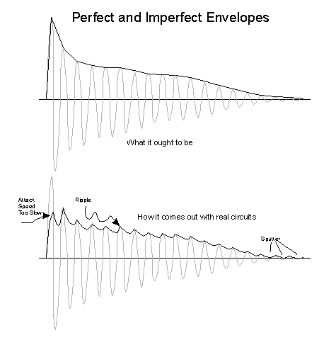 It turns out
that generating a perfect outline of any note is hard. The commonest thing to do
is to half wave rectify the signal with an electronic precision rectifier. The
sketch at left shows what you'd like to get versus what you actually might get
in actual circuits.
Practical envelope generation circuits have to filter the
rectified envelope to get the envelope not to sag between peaks in the signal.
That filtering also slows down sensing the attack. Filtering ripple and having
fast attack response are diametrically opposed, so there is often a compromise
in practical circuits for losing some attack and enduring some ripple.
This compromise hurts at the end of a note as well, where the
ripple might sag below the point where the circuit thinks there is a note, then
get pushed up by the next peak. This can make for some sputtering uncertainty
about the end of a note.
It helps to full wave rectify the signal. This flips the
negative peaks up so that they charge the envelope filter between the positive
peaks. This cuts the ripple on the detected envelope in half, allowing less
filtering and therefore quicker response to the real instantaneous loudness.
There is even a double fullwave rectification technique that
first full wave rectifies the signal, then blocks out the DC component and full
wave rectifies the already full-wave signal. That effectively quadruples the
peak frequency compared to the original signal and dramatically improves the
ability to follow transients while still reducing ripple. The point of all this
is to get an accurate "outline" of the loudness of the note at any
moment.
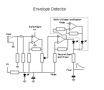 One practical
circuit for generating an envelope is shown at left. This is a cleaned up and
fortified version of the envelope detector in simple auto-wahs like the Seamoon
Funk Machine or the EH Dr. Q. The first amplifier buffers
the raw signal and adds some gain - raw guitar signals are usually too small for
good envelope signals, so we have to multiply them up a bit. The bias voltage
for the first amp is generated either by an LED or a string of diodes. The use
of diode forward drops for inserting a constant voltage drop is a common
technique for voltage offsets inside integrated circuits, and a handy trick to
have in your circuits "toolbox".
The second opamp is fed through a sensitivity pot from the
output of the first. This control lets us adjust the scale of the final output
envelope to take into account the variation in levels from signal sources. The
second opamp's output feeds the amplified signal through another similar LED or
diode string to subtract off the equivalent of the first bias voltage, and the
then half wave rectified signal id dumped through a current limiting resistor
into a capacitor filter. The capacitor voltage is then the output envelope. Note
that the loading on the capacitor determines the speed of the capacitor voltage
decline, and therefore both the size of the ripple in the envelope, and the
speed that the capacitor can decline to follow sudden cut-offs in notes. Some
envelope filters add an explicit loading resistor to control the decay time of
the note as well. Even more elaborate filters than the single capacitor can be
used as well.
The components in the dotted outline add a second and inverted
half wave rectification, to give an effective full wave rectification if
desired.
There are many ways to do a low voltage half or full wave
rectifier/filter. This one is illustrated just because it's simple and easy to
work with.
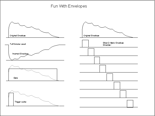 Having spent all
that effort getting an envelope signal, what good is it?
This is the fun part. You can do anything you're clever enough
to design. For instance: the original envelope or its inverted version can be
fed to a voltage controlled filter. This is what is done inside the Mutron III
auto-wah filter. A simpler version is done by the Seamoon Funk Machine, the EH
Dr. Q, and others.
A technique that's easy but not commonly known is to use some
other signal to time-slice the envelope signal itself with some other signal. The envelope represents a kind
of raw loudness signal. You could divide the basic guitar signal in a digital
divider and use *that* to chop the envelope, so you'd have a bass octave down
that has loudness that follows the original guitar's loudness more like a real
bass. You could do the same for a phase locked loop note follower and generate
thirds, fourths, fifths above and below the original signal that also follow the
original guitar's signal loudness. Both of these techniques have been used in
commercial pedals.
If you want to know when there's a note and when there's not,
you feed the envelope into a comparator with a reference voltage just above
zero. That makes a "gate" waveform that is high when the note is
louder than the threshold. That can be the basis for a noise gate. It can also
be used to turn on some other circuit for just the time the note sounds. By
taking the "gate" waveform through a resistor to a capacitor to
ground, the capacitor voltage would rise from zero toward the max gate voltage -
it's an attack delay, with a rise speed controlled by the resistor. A little
wave-shaping can also give you a trigger pulse that indicates when a note has
just started.
The Slice-O-Matic envelope scheme lets you pick off the time
periods when the loudness is between two levels.
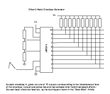 This is one
version of a Slice-O-Matic. The National Semi LM3914 has on-chip references and
comparators to select one of ten outputs when the input voltage to the chip is
at levels in the programmed range. Feeding an envelope signal into the chip
gives up to ten output signals, each low during only a small portion of the
envelope.
Here are some circuit ideas for using envelope information.
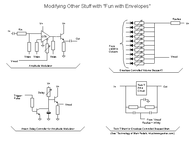 The
amplitude modulator is pretty much the variable gain section from a Dyna-Comp
compressor, which was in turn lifted from an RCA application note for the
CA3080. The gain of the modulator from input to output is linear with the amount
of current going into the control pin, which is in turn controlled by Vmod
divided by the variable resistance as shown. If you fed a solid sine wave into
the input and fed a guitar note's envelope into the modulation input, you'd get
a monotonous series of sine wave tones that were shaped like guitar notes. Dull.
But, if you instead fed the guitar's own signal into the
modulator, and attached the attack delay circuit to the gain control, you would
get a note that started with no gain, then ramped up as the capacitor to ground
under the delay resistor charged it. In effect, you've rewired a Dyna-comp into
an attack delay.
If you take the many outputs of the Slice-O-Matic circuit and
connect them all through variable resistors to the capacitor junction of a Twin
T wah, you get a stepped wah sound as each one is switched in and out.
Other applications that come to mind:
Use the trigger pulse to *stop* the oscillator of a simple
tremolo, like the EAN Tremolo, using
just the resistor and transistor from the attack delay module, you get a weird
tremolo that always starts a note being off (no tremolo), and then the tremolo starts up as
you hold the note.
The gate, envelope and reverse envelopes can turn on other
sounds, like a noise generator, drone oscillator, anything else you want turned
on.
We haven't touched the frequency part of note processing yet.
There's some good stuff to mine there, too.
 So what's in a
note? The sketch at left shows what might be an idealized version of an
archetypical note. The very first signal we get, starting from nil, is a loud
transient. This might correspond to the pick attack, when a guitar pick pulls
the string massively further than it will vibrate normally. That initial
loudness attack decays very quickly to the sustaining level of the note, where
the note volume decays at a slower rate. When the musician ends the note, there
may be other mechanisms that make the note sound for a little bit after the
musician ended it. This is usually a much faster die off than the sustain part
of the note.
 It turns out
that generating a perfect outline of any note is hard. The commonest thing to do
is to half wave rectify the signal with an electronic precision rectifier. The
sketch at left shows what you'd like to get versus what you actually might get
in actual circuits.
 One practical
circuit for generating an envelope is shown at left. This is a cleaned up and
fortified version of the envelope detector in simple auto-wahs like the Seamoon
Funk Machine or the EH Dr. Q. The first amplifier buffers
the raw signal and adds some gain - raw guitar signals are usually too small for
good envelope signals, so we have to multiply them up a bit. The bias voltage
for the first amp is generated either by an LED or a string of diodes. The use
of diode forward drops for inserting a constant voltage drop is a common
technique for voltage offsets inside integrated circuits, and a handy trick to
have in your circuits "toolbox".
 Having spent all
that effort getting an envelope signal, what good is it?
  This is one
version of a Slice-O-Matic. The National Semi LM3914 has on-chip references and
comparators to select one of ten outputs when the input voltage to the chip is
at levels in the programmed range. Feeding an envelope signal into the chip
gives up to ten output signals, each low during only a small portion of the
envelope.
 The
amplitude modulator is pretty much the variable gain section from a Dyna-Comp
compressor, which was in turn lifted from an RCA application note for the
CA3080. The gain of the modulator from input to output is linear with the amount
of current going into the control pin, which is in turn controlled by Vmod
divided by the variable resistance as shown. If you fed a solid sine wave into
the input and fed a guitar note's envelope into the modulation input, you'd get
a monotonous series of sine wave tones that were shaped like guitar notes. Dull.