Copyright 2000 R.G. Keen. All rights reserved.
The idea of modularity is a powerful one. You can make modules suitable for other applications by splitting the functional blocks out of other, integrated effects. Case in point: the Electro Harmonix Dr. Q. This is an auto filter or auto wah, and it consists of two blocks, an envelope detector and a controlled filter hooked together in one circuit. By separating the two into an envelope detector module and a voltage controlled filter, we can do different things with both modules, as well as ganging them together in FXBus to be a Dr. Q. For instance, the envelope detector could also be used to drive a "gating" module for noise reduction or for a backwards-tape effect, or to drive the speed of an LFO. The VCF could be driven by a separate LFO to get a wobbled wah effect.
(Note: in doing this, I have borrowed from changes to the Dr. Q circuit suggested by Mark Hammer and modifications published by Jack Orman in his "Dr. Quack" project. On top of this, I've added a couple of changes of my own, as well as splitting the circuit into independent modules.)
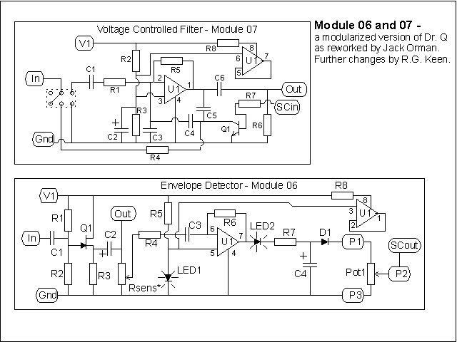
Here's the pair of schematics for the two split modules, with I/O pads for the FXBus connections identified. Notice that the envelope detector, Module 7, should be first it the FXBus chain, as it buffers the input signal and redrives the signal into the next FXBus "In" point, and also generates the "SCout" sidechain signal that modulates the filter response of the VCF.

Here are the parts values, and what each part does for the VCF: (caps in uF unless noted; pots are audio taper unless noted)
| Component | Value | What it does |
| R1 | 47K | Sets the input filter gain in one of the input modes; see "Input Modes and Jumpering" |
| R2 | 47K | With R3 sets a bias voltage for U1 to keep it operating in its linear region, not distorting. |
| R3 | 47K | See R2 |
| R4 | 47K | Sets the input filter gain in the other of the input modes; see "Input Modes and Jumpering" |
| R5 | 470K | Feedback resistor for U1; keeps U1 DC balanced, and with other parts controls the gain of U1; this affects signal gain and the filter Q or sharpness. |
| R6 | 47K | "Pull down" resistor from the original effect to prevent pops when the effect was switched. |
| R7 | 22K | Converts the filter control voltage to a current for changing the collector resistance of Q1 |
| R8 | 33 | Isolates the DC power to U1 from electrical trash that might be on the V1 power bus, and limits the current available to U1 under fault conditions |
| C1 | 0.047 | Couples signal into the circuit in one input mode, see "Input Modes and Jumpering" |
| C2 | 10 | Filters the bias voltage to U1 to keep it noise-free. |
| C3 | 0.001 | One of the filter's frequency-determining capacitors |
| C4 | 4700pF | One of the filter's frequency-determining capacitors |
| C5 | 4700pF | One of the filter's frequency-determining capacitors |
| C6 | 0.047 | Output capacitor, couples the filtered signal to the output line. |
| U1 | dual opamp | Most any dual opamp; TL072, 4558, 1458, LM833, all work well; I picked a dual opamp even though only one section is used because they're about as cheap as a single, and duals are useful for other projects as well, so you can get them cheaper by buying in higher quantity. In the future, I may rework the circuit to use the unused section. |
| Q1 | NPN | silicon NPN transistor; 2N5088 and 2N3904 will work fine, usually; the resistor's variation in collector resistance with applied base current is what causes the filter to sweep |
Here are the parts values, and what each part does for the Envelope Detector: (caps in uF unless noted; pots are audio taper unless noted)
| Component | Value | What it does |
| R1 | 1M | With R2, establishes a DC bias point for buffer transistor Q1 |
| R2 | 1M | With R1, establishes a DC bias point for buffer transistor Q1 |
| R3 | 10K | Source resistor for Q1; buffered signal appears across this resistor. |
| R4 | 47K | With R6 and C3, determines the gain of the envelope detector after the sensitivity control sets the sensitivity level |
| R5 | 10K | Sets the current through LED1, which provides a bias voltage for U1. |
| R6 | 470K | Feedback resistor; with R4 and C3 sets the gain of the envelope detector. |
| R7 | 100 | Limits the current pulses into C4, and has an effect on the attack characteristics of the envelope. |
| R8 | 33 | Isolates the DC power to U1 from electrical trash that might be on the V1 power bus, and limits the current available to U1 under fault conditions |
| Rsens | Adjusts how much of the buffered signal drives the envelope detector; this allows for varying how much envelope you get for a given signal level. Rsens is set up for three different options on the PCB. It can be one of two styles of miniature trimmer pot with an adjustment screw at the top of the PCB, or two fixed resistors if you don't need adjustment. | |
| C1 | 0.047 | Couples input signal into the circuit from the "In" line. |
| C2 | 10 | Couples the buffered signal to (a) the "out" line for driving the next module's input and (b) drives Rsens, the envelope sensitivity control. |
| C3 | 0.047 | Couples the AC signal into U1 and blocks the bias DC level from being affected by Rsens. |
| C4 | 10 | Filters the rectified positive going signal pulses into an "envelope". |
| U1 | dual opamp | Most any dual opamp; TL072, 4558, 1458, LM833, all work well; I picked a dual opamp even though only one section is used because they're about as cheap as a single, and duals are useful for other projects as well, so you can get them cheaper by buying in higher quantity. In the future, I may rework the circuit to use the unused section. The most obvious uses are to buffer the envelope out or to invert the output of the first opamp to convert to a full-wave rectified envelope detector for smoother results. |
| Q1 | N-CH JFET | An N-channel JFET used as a source follower. This presents a high impedance to the incoming signal to avoid loading it, and a low output impedance to drive the envelope detector as well as the "out" line to drive the following module. |
| LED1 | The typically 1.5 to 2.2 volts across the LED sets a low but stable bias level for U1 slightly above ground. LED2 effectively "subtracts" a similar amount from the output so U1 acts like it's operating closer to ground than it really is. LED1 and 2 MUST be alike for best results - e.g., both same manufacturer, same color. | |
| LED2 | Subtractor LED; see LED1 | |
| D1 |
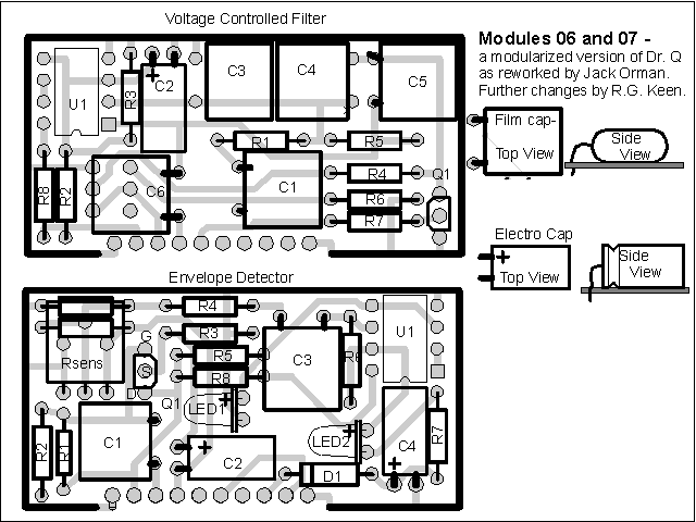
And how they're laid out:

Notice the group of six pads under C6 on Module 6, the VC Filter. These jumpers control the filter mode in the original Dr. Q. One position is marked "Bass", presumably indicating that the filter response is lower in range. What this really does is to change the actual mode of the filter from a "multiple feedback" type to a Twin-Tee style, so the same capacitors give a different frequency range. You MUST put in two jumpers for the filter to work at all. A pair of jumpers must go between the middle pads to the pads immediately above, or for the other position to the pads immediately below.