Copyright 2000 R.G. Keen. All rights reserved. No permission for posting from web sites other than http://www.geofex.com.
I run into this a lot, so I decided to draw it up. Sometimes you are trying to fix a problem with an amp or other equipment that you're concerned might have a power fault. The worst thing that can happen is that when you turn it on, it immediately pops a fuse - or worse yet a valuable part you've just installed! If you don't have a variac with a current meter so that you can make power on gradual, the next best thing is this widget. It can be whipped up from parts in your local home supplies store.
NOTE: YOU MUST BE ABLE TO SAFELY WIRE AC POWER OUTLETS TO DO THIS. DO NOT ATTEMPT THIS IF YOU DO NOT ALREADY KNOW HOW TO DO SUCH WIRING SAFELY. IT'S TOO DANGEROUS OTHERWISE.
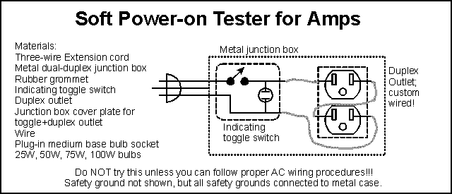
The following diagram shows the materials and wiring.

To build it
1. Knock out one of the plugged holes in the junction box. Install a grommet into the hole.
2. Cut off the female end of the extension cord. Insert the cut end into the grommet. Strip back 4" of outer covering from the wires inside and then strip 5/8" of insulation from each wire.
3. Connect the black wire to the Line or "L" terminal on the indicating toggle switch. Connect a black wire between the switched line terminal of the toggle switch to the "L" terminal of one of the duplex outlets. Mark this outlet on the outside of the outlet so you can select this one from the other outlet later.
4. Break off the tabs connecting the two outlets in parallel. Identify the "N" or Neutral side of the outlet whose L terminal is connected to the toggle switch. Connect a black wire from this "N" terminal to the "L" terminal of the second outlet.
5. Connect the white wire from the cut end of the extension cord to the "N" terminal of the toggle switch and another white wire to the remaining "N" terminal of the second outlet.
6. CONNECT ALL GROUND TERMINALS AND THE GREEN WIRE OF THE EXTENSION CORD TO THE METAL JUNCTION BOX. THIS IS A CRITICAL SAFETY STEP. BE CERTAIN THAT THESE CONNECTIONS ARE FIRM AND SOLID.
7. Recheck your wiring. Then put the metal cover for the junction box in place. Install a light bulb into the plug-in socket base and plug it into the marked "hot" outlet. Operate the toggle switch to verify that the indicator goes on and off properly with the toggle switch. plug a known-working amplifier into the remaining outlet and turn the toggle on. Turn the amp to standby while watching the lamp. The lamp should flash and then glow an amount that reflects the "idling" drain of the amplifier. For the 25W lamp, this may be fairly fully on. For higher wattage bulbs, this will be dimmer.
To use the tester, plug the amp under test into the outlet, and choose a bulb. If you've had shorted-AC or fuse-blowing problems, you may want to use a 25W lamp, as this will limit the AC current to a bit under 1/4 ampere. This should allow you to verify that you've fixed the problem without losing any more fuses! If you're debugging a runaway problem where normal operation starts OK but then things get hot, you can use a larger wattage bulb to allow semi-normal operation of the amp but to choke off the AC as the runaway starts. The lamp will glow more brightly as the amp tries to draw more current.