Resurrecting a Thomas Vox Beatle From The Bare Metal
Anyone who's listened to my tirades about the design issues with Thomas Vox Beatles will be familiar with the problems. They are not electronically robust, as we see things today. Worse yet, they're hard to fix - sometimes almost impossible even for a skilled repair tech. But I do like them a lot. What to do? Live with a possible disaster waiting to happen?
I took the other approach. I kept the circuit designs, updated them for reliability, then did a new set of PCBs that fix (I hope!) the reliability problems.
I was lucky enough - if that's the right word - to get a real bargain on some empty Thomas Vox sheet metal. These were just the sheet metal, stripped right down to the bare metal. Here's where I started:
![]()
As I said, just the bare sheet metal. What is normally inside is this:

As you can see, it's going to be challenging to work on. To deal with any switch or jack problems (and this is a very likely thing to happen) you must loosen the PCB and bend it up out of the way, like this:
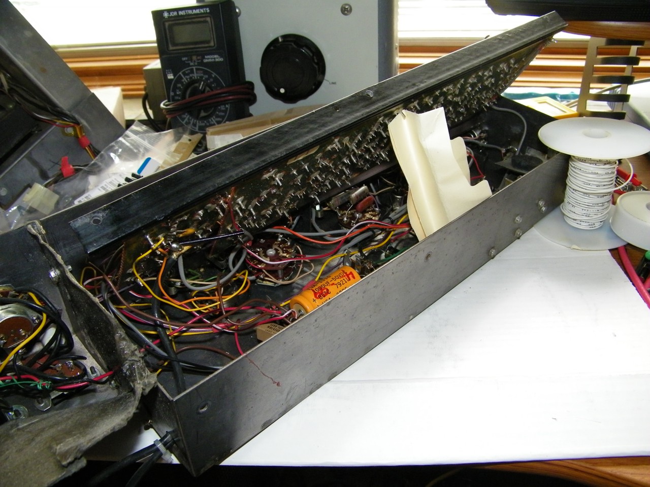
I've shown it in the only good working position, propped up with a bit of folded-up manilla file folder. What you really, really don't want to do is to bend the board up further so you can really get at the stuff hidden under it. Unfortunately, this is what a tech may do first on his first time into one of these amps. The amp may never recover from that. That's because Thomas built the wiring harnesses out of solid-core copper wire, and stripped the insulation with mechanical cutters. That process unavoidably nicks the copper right at the end of the insulation, setting up a pre-made invitation for the wire to break at that point. It would not be so bad if there was only a few wires, but there's a bundle, and they are tied together in that bundle, so the joints get stressed with each flex of the wires. It only takes a few times. It is possible to fix the broken wires, but you have to do it in a way that fixes them faster than they break. The more times you bend those wires to get under the PCB, the more times the wires get flexed, and the more of them break. Many techs simply refuse to service these amps, largely as a result of this very issue. It requires something of the surgeon's skills, and taking your time. Time is money to a tech, and he'd really rather pop in a new set of tubes and rebias than perform surgical procedures. And I can't blame him.
The key if you ever have to work on one of these amps is to bend those wire **once** to get it into the position shown. Do 100% of everything you're going to do without ever waving that PCB up and down again, and pray that a wire does not break as you fold it down into place to button it all up after fixing it.
If you can get past that, the amps are not terribly complex or hard to get working. There's just lots of wires. Did you ever see the play or the movie "The Mousetrap"?
This leads to my standard advice: if your Thomas Vox amp fails, replace everything inside it that even might need replaced when you open it up that once. If you do that, it may last to pass down to your grandchildren. If you don't, there is a good chance that it's ready to be buried when you get through with the first "repair".
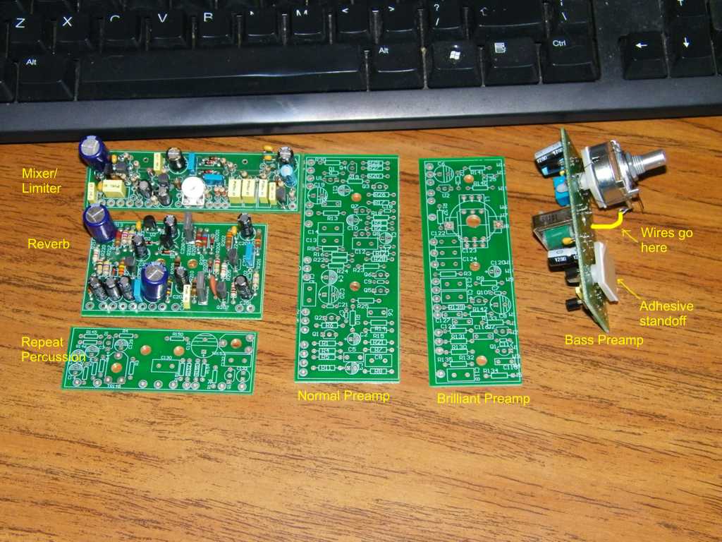
That chain of reasoning led me to side step the wire issues in a manner somewhat doing a well-executed veronica. (look it up). I took the circuits, which I like to listen to, and separated them into a plethora of little circuit boards where all the wires to the controls are about 2" long and mounted the PCB on the controls. There remains the same number of wires, more or less, but they are (a) short and (b) isolated from one another so that fixing one thing probably does not kill something else.
Another oddity surfaced in working on the boards in the shell: rocker switches for the "brilliant" and "MRB" functions are no longer available. I had expected trouble with the rotary switches for the power, MRB frequency, and reverb assignment controls, and had worked out a substitute. But the rockers stumped me for a bit. the bottom line is that all affordable rocker switches are press-in, not screw-mounted like the old ones.
Here's what I came up with:
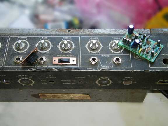
I found rockers which were small enough to go through the rectangular hole that's already in the chassis, and then made mounting tabs which will bolt to the existing holes from the back. A little work with a drill press, jeweler's saw and file gave me the two rocker switches you see. That's the reverb circuit board beside the controls. The metal strips will be painted black when I get ready to clean up the aesthetics.
The power switch presents some problems. it has to withstand 125Vac line voltage, but must also pass the 11-12A peak speaker currents. They don't make rotary switches like that which are under about $50.00 each any more. I settled on a 4P3T rotary switch rated for 1A at 125V, which would do the job for all three rotary switches for $5.00 each. To handle the current, I found SPDT miniature relays with 125Vac coils. These will go on a small PCB mounted to the chassis by the power rotary switch. A little care in the PCB layout gives the same off-stby-on as the original. I had expected problems with the indicator lights. But replacement 125Vac neon indicators were available in red and green for under $1.00 each, and fit the same holes.
I'll post more pics as I get further along with the resurrection.