| When you get tired of paying for batteries for your
effects, you start thinking about getting a wall wart to run your
effects. Here's some info on what's going on with those power supplies
and how to think about designing your own.
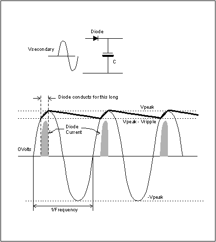
Let's start simple. What happens when we rectify an AC signal? From the picture at the right we can dope most of it out. Vsecondary (which we will pretend is a sine wave coming out of a transformer secondary, hence the name) is fed into a simple diode-capacitor rectifier/filter. We'll pretend there is some load in parallel with the capacitor, taking current out of the capacitor on the right hand side of the circuit. When the Vsecondary is higher than the voltage on the capacitor by more than one diode drop, the diode conducts and a big pulse of current flows. This supplies the current to the load, but also charges up the capacitor to very close to the instantaneous secondary voltage. It's less than the secondary voltage peak by only the diode voltage drop. As soon as the AC voltage reaches its peak and starts down, the diode becomes reverse biased and turns off. Now any current going to the load is supplied by the capacitor. The voltage in the capacitor runs down over a period of time until the secondary voltage once again becomes more than the capacitor voltage. From the fundamental capacitor equation, I =C*dv/dt, or dv = (I*dt)/C For small amounts of voltage sag, we'll pretend this is linear, so the amount of sag (dv) will be the load current times the period of the AC line waveform, divided by the capacitance. The amount of voltage that the DC on the capacitor runs down and is then recharged is called the ripple voltage. All of the current expended in the load during this longish time has to be reloaded into the capacitor during the shortish time that the diode conducts, so the diode current peak is very high, many times the average current into the load. The half wave rectifier works, but it completely wastes the unused
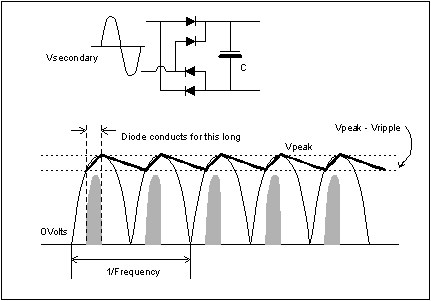
half of the AC wave. We can do better. The full wave bridge rectifier does this, at the cost of three additional diodes. If you follow the arrows of the diodes, you can see that the diodes cause both polarities of the AC secondary wave to look positive to the capacitor. This changes things a bit. First, the rectified half waves come twice as frequently. That means, for a constant load, the voltage in the capacitor only runs down half as far before being recharged. Alternatively, for the same ripple voltage, we can use half as much capacitance to smooth the DC out. Second, the diode current peaks come twice as often, so they're only half as high, on average. Predicting the diode peaks is difficult in all rectification systems. Tiny changes in the diode forward voltages can make big changes in the relative current peaks, so it's best just to think of them as many times the average load current. There are so many practical advantages to full wave rectification that no one does anything else unless there are some incredible practical advantages in other areas to NOT doing it and doing half wave instead. So how do you figure out how much secondary voltage you need to have to get a specified output voltage? Easy. Let's say we want 12Vdc out at the filter cap. If that's 12V before ripple voltage (because ripple you have with you always) you need 12Vdc plus any ripple voltage you choose to allow, plus two diode drops (for full wave rectification). That's the peak of the AC secondary wave: Vsecondary(peak) = (Voutdc +Vripple + 2*Vdiode) To convert that to AC RMS voltage, we divide by 1.414. That factor is the observed ratio of the peak to the RMS value of a sine wave; so Vsecondary(rms) = Vsecondary(peak)/1.414 You get to choose how little (or big) a Vripple you want to pay for. Because Vripple = Iload*(dt/C) you can make Vripple as small as you like for any load current by recognizing that AC line supply voltages are a fixed frequency, and dt is going to be about 8ms for 60 Hz line voltages, and about 10ms for 50Hz line voltages. With dt fixed, you can have as low a ripple as you want to pay for capacitors to make. That can get out of hand, of course, but the potential is there. In doing this, there are a couple of gotchas that you need to think
of after you get the design sketched out. AC line voltage is NOT
constant. It varies about +/- 10%. So if you are needing at least some
certain voltage, calculate the minimum voltage you need, add 10% to it
and decide how to cope with the added voltage in the normal case. On top
of that, transformers are NOT perfect. That is, they have internal
resistance and voltage losses. In the transformer biz, the voltage loss
from zero load to full specified load is called the
"regulation" -not the same as voltage regulation, but a pure
resistive loss just because the transformer is there. Regulation is
worst in small transformers. That's why wall warts rated at "12Vdc
at 500ma" are 16Vdc a zero load. The maker designed it to be
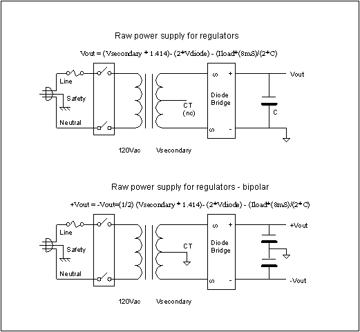
sure it would make AT LEAST 12Vdc with a full 500ma load. But we're going to use regulators - so here's what to do there. The normal three terminal regulators need at least two volts across them to do their regulation, so the minimum voltage you should design the DC supply for is Vregulated + 2. That is, for a 9V supply, you need at least 11Vdc, and that's at -10% line, you remember. So Vsecondary is about Vsec = (11 + 1.4)/1.414 = 8.779V, ignoring ripple voltage. At normal line that is 8.8*1.1 = 9.65Vrms We can't really ignore ripple safely, so we need to add some more. 10Vac to 12Vac is a good place to start. The top picture at the left is a good schemo for the basic power supply. You can use a 10Vac or the more common 12Vac transformer (with or without a CT, the CT is not connected). You can then calculate the size of capacitor to buy based on your load current. If you are making both positive and negative regulated voltages, you have to make both positive and negative bulk DC supplies. That's when that CT gets useful. The CT is a wire that is guaranteed to always be exactly in the
center of whatever the two outside transformer leads are doing. So if we
connect the DC to something we'll call "ground", and also put
two filter caps in series at the output of the diode bridge with
"ground" connected to their common junction, we have two DC
power supplies, each full wave rectified, and symmetrical around what
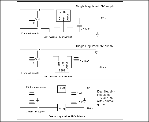
we're calling "ground". Now to the regulators. Three terminal regulators are a breeze. They can with stand up to 40V on their input terminal, they put out the specified output voltage within about 5%, maybe better, and are self limiting for current and thermal problems. All they ask is that you feed them relatively clean DC at least 2V higher than you ask them to put out, and that you put a capacitor on their output to help keep them stable. The schemos shown at right do this. You can make a single + regulated voltage from a bulk DC supply, a single - regulated supply from the same supply, different connection (middle schemo) or if you have played with the CT and produced a bipolar bulk DC supply you can make BOTH a positive and negative regulated supply from the same bulk DC supply. Have you found the error in the bottom schemo? Notice it says that Vsecondary must be 11Vdc minimum. That's not quite true. The +V and -V from the raw supply has to be sufficient to make +11Vdc and -11Vdc, so Vsecondary will have to be 20Vct at a minimum, and a 24Vct would be easier to find. There's an alternate but cruder way to make bipolar raw DC supplies for regulators.
There is another trick that will NOT work that gets tried once in a while. Sometimes a clever guy will come up with the idea to use two full wave diode bridges to full wave rectify a non-CT transformer secondary in two isolated DC outputs, then connect the + end of one to the - end of the other, reasoning that the diodes will isolate them and everything will be cool. That does not work. The two diode bridges themselves wind up shorting the transformer secondary, and lots of smoke escapes.
Send mail with questions. |
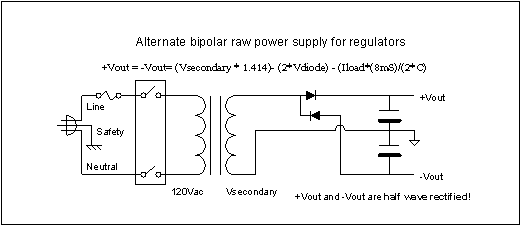 In the schematic at
the right, the two diodes each half wave rectify the transformer output,
but to two different capacitors. This circuit is the same as the
so-called half wave voltage doubler. It's only real advantage is that it
can make a bipolar power supply out of a non-centertapped transformer
secondary. The outputs still need twice the capacitance that a full wave
rectified output would.