Copyright 2000 R.G. Keen. All rights reserved.
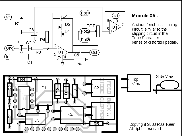
Module 5 is a feedback diode clipper - that is, it does distortion by putting diodes around the feedback path of an opamp. This is very similar to the clipping stage of Ibanez' Tube Screamer series. For a detailed discussion of the workings of a feedback diode clipper, see "The Technology of the Tube Screamer".
Here's the schematic and layout:

Here's the parts list and what each part does (Note - caps in uF unless noted; pots are audio taper unless noted):
| Part | Value | Notes |
| R1,R2 | 10K | Create a 4.5V bias supply for U1 |
| R3 | 4.7K | with Pot 1 and C2 determines the gain and rolloff properties of the clipper |
| R4 | 510K | Feeds bias current to the input of U1; must be large to prevent loading signal |
| R5 | 510K | "Pull Down" resistor for output capacitor C5 |
| D1, D2 | The clipping diodes - their conduction voltages determine where positive and negative clipping occur | |
| C1 | 0.022 | Input capacitor; also helps determine the point at which bass input is rolled off |
| C2 | 0.047 | DC blocking capacitor on feedback loop; with R3 helps determine the bass response of the clipping amplifier U1. |
| C3 | 10 | filters the bias voltage created by R1, R2 to prevent noise. |
| C4 | 47pF | feedback capacitor to cut higher harmonics from the clipped sound |
| C5 | 0.022 | output capcitor, couples the clipped signal to the output pin |
| U1 | Dual opamp | JRC4558 is highly thought of, but LM833, TLC2202, and others work well too. Only one section of the dual opamp is used; this is because duals are almost as cheap as singles, and easier to lay out. |